
If you spend any time in the Raspberry PI world, then you probably know about this project and the vast number of resources on how to complete it. When I attempted to follow some of them for this project, I had to look between a few to get it working. I also wanted a power switch to make shutting it down or booting it up easier, I’ll outline the whole process start to finish including my additions below.
You will need:
- Raspberry Pi Zero
- A Male USB connector
- Wire
- Momentary switch
- 8gb or more micro SD Card
- Zip ties
- Hot glue
- Bushings (the height f your USB connector)
- Electrical tape
- Scrap plastic
- Fine point marker
- Razor blade
- Drill bit
Setting up the hardware.
I found a couple versions of this project. Some used the USB port area of the Zero’s board and some used the GPIO positive and negative ports and just the data pads that are easily accessible below the micro USB port. I went with the later because it was a little more accessible in my opinion and I’m not planning for the use of the GPIO’s at this time.

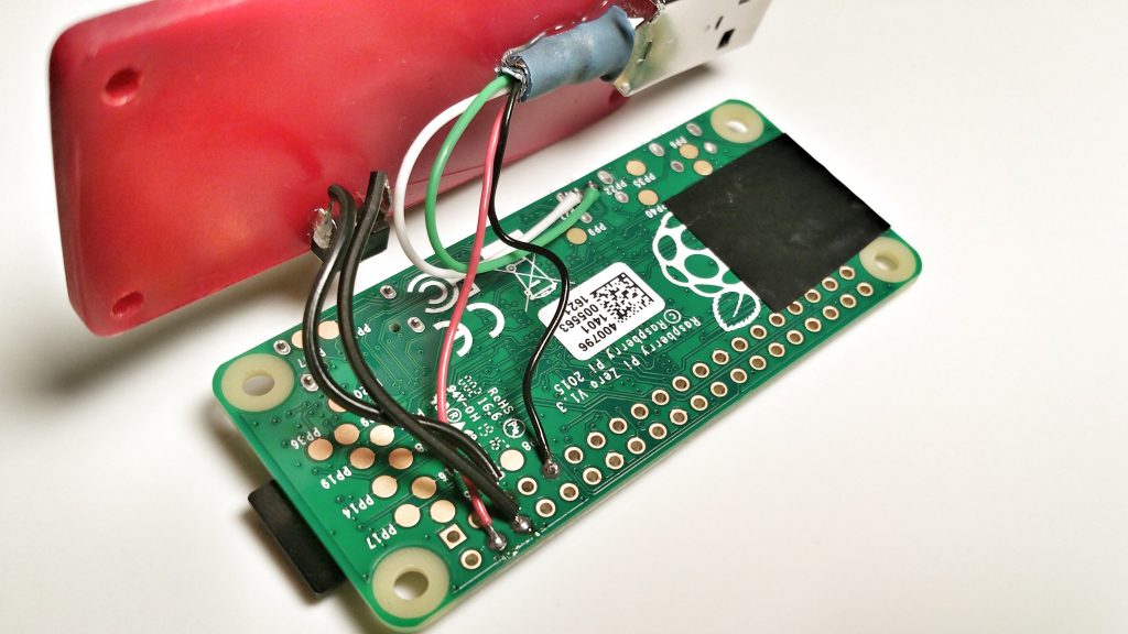
I scavenged my USB cable from an old iPod charging cable so it had the wires already connected to the male plug. I just stripped the shielding and trimmed it up to the wire length I needed. You can use a male plug and solder wire directly to its inputs and then to the Zero.
- Solder the Red cable to the 5v GPIO location.
- Solder the Black cable to the Ground GPIO location.
- Solder the two Grey wires to the GPIO locations (they are interchangeable)
- Solder the White USB data cable to the PP23 USB data location.
- Solder the Green USB data cable to the PP22 USB data location.
- Place a piece of Electrical tape on the Zero below the USB plug location.
Note – Remember keep the male USB plug in the correct orientation, with the filled white holes facing you. This will ensure that when the bottom cover is added and the unit is flipped over, that it will plug into the USB ports on your computer as expected. Also keep in mind that if you need to solder the wires to the USB male plug that this will ensure that the wires are attached to the proper pins.
Making the case.
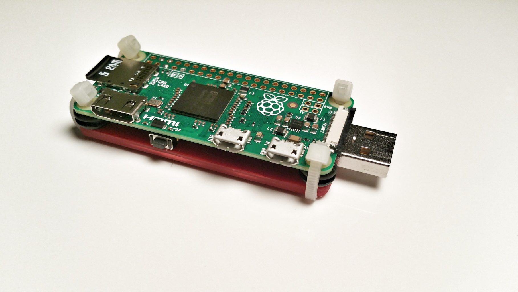
I noticed that most people making these dongles only shielded the bottom of the unit and basically sandwiched the male USB plug between the case and the Zero so I did the same in my project. I used the “case” as the glue point for my male USB plug.
- Trace the outline of your Raspberry Pi Zero with a marker over the plastic including the holes on all 4 corners.
- Cut out the outer shape using a razor blade.
- Drill out the four holes at the four corners.
Putting it together.
Once you have the pieces all together and everything is ready for assembly, this is the order I followed.
- Hot glue the male USB plug to your case. This is where the anchor will be for inserting and removing the USB drive so that it stays together.
- place a piece of electrical tape opposite to the USB plug on the Raspberry Pi Zero board to cover the contacts and prevent shorting out the Zero.
- Add a bushing to each corner between the case and the Zero as you run your zip tie through each corner leaving them loose.
- Tighten them a little at a time to keep everything even. They should be just snug enough to keep everything from moving around but not so tight that they bend anything.
- Clip the excess zip tie material.
Installing the OS.
So far I’ve only seen this done with the current Raspbian release found here. I used a 16gb micro sd card but you could probably work with something in the 8gb or up range. You will also need to install Win32 Disk Imager found here if you are using a PC . You will need to find a solution for Mac or Linux which I can help you with if you leave a comment requesting this below.
 Unzip the Raspbian image.
- Open Win32 Disk Imager.
- Select your Rasbian image file.
- Select your Device (micro sd card) drive letter.
- Select Write and wait for the process to complete.

Modifying the OS.
To get the Zero to boot as a USB “dongle” device, you will need to modify a couple of files that are located on the newly written micro sd card. Navigate to the drive using windows explorer and you should find them in the root folder.
Edit config.txt
Open config.txt with notepad and add the following to the end of the file:
dtoverlay=dwc2
Save and close config.txt.
Edit cmdline.txt
Open cmdline.txt and look for the word “rootwait” and type the following just after it:
modules-load=dwc2,g_ether
Save and close cmdline.txt.
As a note, make sure that there is only one space before and after the line of code to ensure that it works properly.
Setting up your PC.
You will need Apples’ Bonjour, iTunes or Quicktime installed on your PC for the dongle to be identified as an RNDIS or USB Gadget on your PC. Make sure that you do have one installed before you move on with the next step.
Booting the device.
This project is a great option for using the Raspberry Pi Zero because you don’t need to have a micro USB adapter for the keyboard or mouse and you won’t need a micro HDMI cable to get things up and running. Adding the few lines of code above will take care of managing this for you but I did notice a few things during my initial attempt with this project.
- Insert the micro sd card into the Zero.
- Insert the device into your USB port on your computer.
- Allow the device to fully boot which can take about 90 seconds.
I’m not sure what happened on my first attempt but for some reason, the device was never recognized by my computer and I had to start over. I re-flashed the OS to the micro sd card and this time just plugged power into the power port on the Zero. I waited for about 90 seconds when I noticed that the lights on the unit stopped flashing and pulled the cord.
This time when I plugged the device into my USB port, my computer recognized it and I was able to SSH into the Zero.
Logging in.
Now that the device is connected to your computer and fully booted, you can SSH into it. I like using Bitvise found here for this because it gives me a few options that Putty doesn’t but either will work.
The SSH login details are:
Host: raspberrypi.local
Port: 22
Username: pi
Password: raspberry
Getting internet access.
To make the dongle more useful, you will want to share your computer’s internet with it. I’ve noticed that my IP address does change on reboot and I’ve seen the Ethernet device number change once so if you ever have an issue with internet on the Zero, try repeting these steps.
- Navigate to Control Panel > Network and Internet > Network and Sharing Center and select “Change Adapter Settings” on the left-hand side.
- Note the connection that says “USB Ethernet X/RNDIS Gadget” which will be your Raspberry Pi Zero. It will be “Ethernet (and some number).”
- Locate the connection that you are using for your internet connection, in my case WI-FI, and right-click on it. Select properties and then navigate to the “Sharing” tab.
- Select “Allow other network users to connect…” and in the dropdown box select your device.
- Select “OK” and reboot your Raspberry Pi Zero.
- SSH to your Zero again and type ifconfig. Under usb0, you should see your “inet addr: 192.168.x.x” which is your ip address for the Zero.
Setting up the power switch.
I wanted an option to allow the device to shutdown gracefully without having to SSH to it if I wasn’t using it any longer. I found the majority of this information at barryhubbard.com and really appreciated his write-up because It’s exactly what I was looking for. I have added my own details as well to make this work with the Raspberry Pi Zero and the current Raspbian.
You will already have these installed if you are using the latest version of Raspbian but you can make sure by running the following.
sudo apt-get install python3-dev
sudo apt-get install gcc
sudo apt-get install python-pip
Next, you will need to download RPi.GPIO. I like to download things in the Downloads folder so let’s navigate to Downloads. This command should work if you haven’t changed your username yet. Substitute your username for “pi” if you have.
cd /home/pi/Downloads
wget https://pypi.python.org/packages/source/R/RPi.GPIO/RPi.GPIO-0.5.11.tar.gz
Uncompress the package with the following command.
sudo tar -zxvf RPi.GPIO-0.5.11.tar.gz
Change to the new directory.
cd RPi.GPIO-0.5.11
Install the module.
sudo python3 setup.py install
Making the script.
We have everything that we need installed to control the power switch. We just need to add a script to let the Zero know what to do when the button is pressed.
First, make a directory where we will keep the script.
mkdir /home/pi/scripts
Next we will create the script in our /scripts folder.
nano /home/pi/scripts/powerbtn.py
Then copy and paste the following into your file.
#!/usr/bin/python
import RPi.GPIO as GPIO
import time
import subprocess

# sets the use of the pin numbering to match the pins on the board.
GPIO.setmode(GPIO.BOARD)

# use the same pin that is used for the reset button
GPIO.setup(5, GPIO.IN, pull_up_down = GPIO.PUD_UP)

oldButtonState1 = True

while True:
    #grab the current button state
    buttonState1 = GPIO.input(5)

    #check to see if button has been pushed
    if buttonState1 != oldButtonState1 and buttonState1 == False:
      subprocess.call("shutdown -P now", shell=True,
        stdout=subprocess.PIPE, stderr=subprocess.PIPE)
      oldButtonState1 = buttonState1

    time.sleep(.1)
Next, we want to make it executable.
sudo chmod 777 /home/pi/scripts/powerbtn.py
Now we need to add the script to rc.local so that it will start when the Zero boots up. You will need to edit the rc.local file.
sudo nano /etc/rc.local
The following should be added just about the line that says “exit 0” which identifies the end of the rc.local file. If it is anywhere else, it won’t run. You can have space above and below the following line.
python3 /home/pi/scripts/powerbtn.py &
Reboot your Zero and the power button should be working once it’s back up.
sudo reboot
Test your button once your Zero has completed it’s boot sequence. When pressed, the Zero will begin shutting down gracefully. You may hear a sound from your computer alerting you that the USB device was removed. The Zero is fully down when the light no longer flashes on the unit. If the button is pressed again, the device will boot up.
(Optional) Configuration
I mainly use my Raspberry Pi Zero as a development and testing platform for web content. You may find these articles useful additions to your Zero project.
Installing LAMP (Linux – Apache – MySql – PHP) On Ubuntu
Raspberry Pi Initial Configuration Using Raspi-Config
Setting A Static IP Address On Raspberry Pi Zero Dongle
Conclusion
That’s all there is to it. You can vary your interpretation of the build with whatever you would like to use. I’m thinking about adding a shield for the top of the unit which I will share if I do complete it.
I’ve not seen a power button on any of the Raspberry Pi Zero projects I came across before. I think it helps the overall usefulness of the dongle and promotes actually shutting down the device.
I use mine all of the time. It’s nice having a Linux box with me anywhere I go. Sure I could carry my dedicated Ubuntu laptop for work (which I do half of the time, an HP Stream 11) or use a virtual machine, which will share my laptops resources, but this really works for me. If you spend any time scripting, use emacs for programming, use a LAMP server or just want to practice, I think you will find it very useful.
Mine is setup as a web server and it is great for development. I can just ftp my files over and test websites. If you decide to do this, make sure to use the Zero’s IP address instead of raspberrypi.local to access your sites as it works much faster.
How do you use yours? Let me know yours in the comments section.


Mass USB storage? It would be neat to have a read only Mass USB storage device which could have content uploaded to the storage device over the network. Power could be drawn from the USB port or an external USB battery pack.
Pingback: How can the Raspberry Pi emulate a USB storage device? – Config9.com